TDR, S parameter, Eye Diagram
TDR diagrams
Diamond Particle Interconnect interposer vs. solder ball
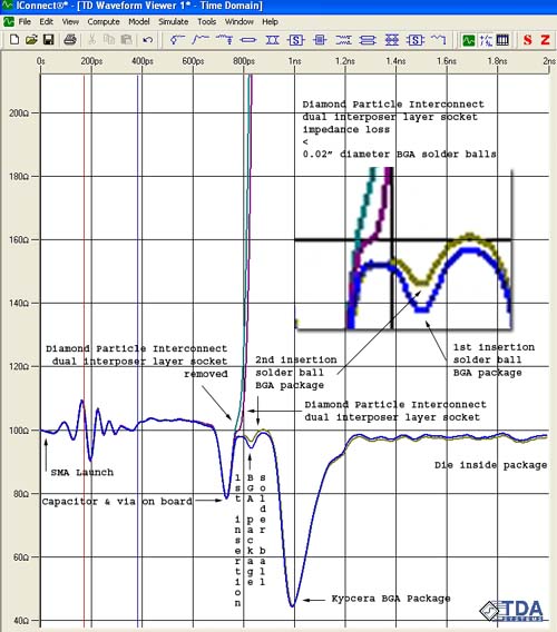
TDR data illustrates zero reactance and remate consistency of Diamond Particle Interconnect socket. TDR data shows that Diamond Particle Interconnect remated connection is better than soldered connection and SMA connector. Solder balls degradation shown in the inset. While Diamond Particle Interconnect is consistent across remates. State of the art Kyocera BGA package has very large impedance discontinuity.
Diamond Particle Interconnect interposer vs. pogo pin
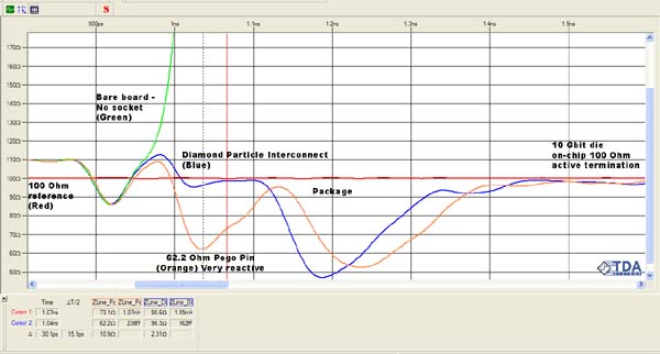
Note the reduced latency of the reflection from inside the package provided by the Diamond Particle Interconnect (blue color graph). Diamond Particle Interconnect performance is better than pogo pin and package.
Eye diagrams
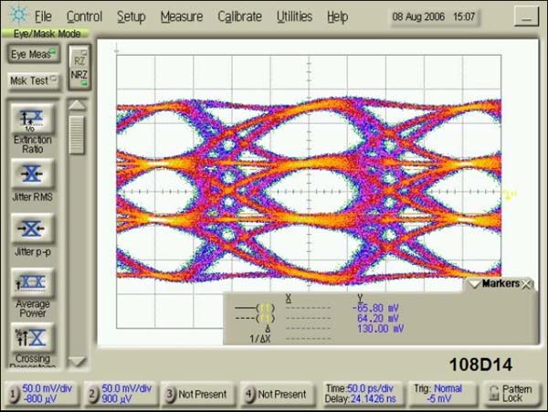
10 Gb/s PAM4 (Programmable Attribute Map) eye diagram
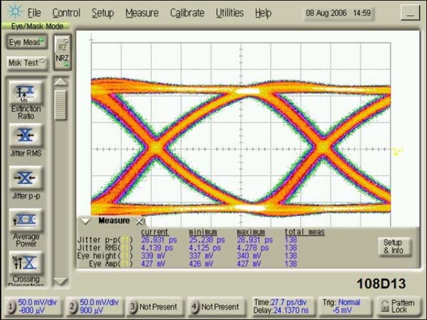
6.25 Gb/s NRZ, PRBS (Pseudo Random Bit Sequence) 231-1 eye diagram
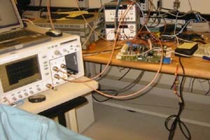
Experimental setup
Particle Interconnect BGA interposer test setup
Nominal losses stem from the typical minimum interconnect surface area for BGA and other MLF type packages. However, the Particle Interconnect interposer minimizes these skin effect losses by maximizing surface area of the conductor (similar to multi-strand wire vs. single strand wire of same cross-section), thereby reducing transmission loss across the connection.
 |
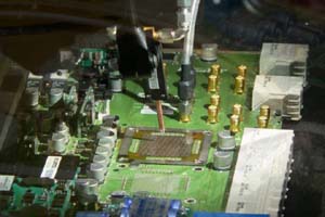 |
| Board | Testing of Particle Interconnect interposer for 676 ball BGA. |
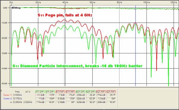
S parameter
Particle Interconnect vs. pogo pin S11 parameters
The measured insertion and return loss shows a 4 GHz resonance at the solder ball causing PCI-X return loss failure below 6 GHZ. By replacing the standard pogo pin socket with Particle Interconnect socket the return and insertion was measured beyond 12 GHz, without modifying the board.
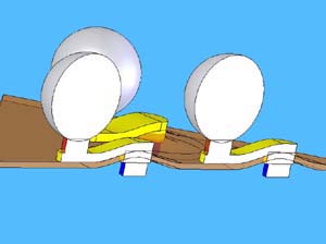
Geometry
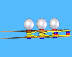
Particle Interconnect BGA interposer geometry
 |
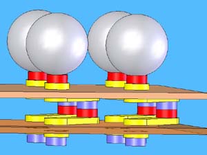 |
| 1 layer deflected PI interposer cross-section | 2 layer PI interposer |
 |
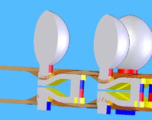 |
| 2 layer deflected PI interposer | 2 layer deflected PI interposer cross-section |